
A Vox VT20+ repair

In 2013 I purchased a used VOX VT20+ guitar amp at ebay for a quite good price (60 Euro). The seller said it had worked fine but suddenly stopped to produce sound at the speaker. The headphone was still working fine. So I thought this would be a minor issue, because I already had fixed a problem in a Vox DA5 without problem.
It turned out that repairing a VT amp is not so easy. With beginning of Vox VT20+/VT40+/VT120+ series it became almost impossible to change defect parts because Vox/Korg have changed the layout in the amp section to using SMD. This makes it even hard to check the device. The pins of the power amp circuit TPA3110D2 have a spacing of 0,65 mm only. So you have to use a magnifying glass to be able to put the probe head on the right pin. Also you must strictly avoid shorting adjacent pins!
It will be a very good idea to look for someone who can help you, looking at the oscilloscope or multimeter while you are trying to pinpoint the pins.
Disassembling the Vox VT20+
Remove rear panel
8 long black wood screws
7 long metric screws on the control panel
Remove control board from the housing
3 black metric screws
Remove yellow + blue (ground) wire off the speaker chassis (7 mm wrench)
Remove both connectors from the speaker
- White / black cable (left = black)
Unscrew transformer
- 4 nuts (7 mm wrench)
- solve yellow cable
Remove connectors from/to main board
- 2x red from the transformer
- White connector located at the input board
- White connector from Foot switch connector
Remove the circuit board from the front panel
- Loosen all screws on back
6 bright metric screws
- Remove all buttons of the rotary switches and potentiometers
- Unscrew all the nuts of pots 12x
Make some photos of the wiring so that you can look at while assembling. There are also some photos at VT20+ user forums and also at www.voxshowroom.com that show the inner parts of the VT20+. Just use a search machine.
Fixing the amp section
Materials needed:
- TPA3110D2 data sheet
- a 100 k resistor
- 7 mm and 10 mm wrench
- phillips head screwdriver
- Soldering iron + solder
The wiring of the output stage in the VT20+ is basing of the circuit for bridge operation, as it is shown in the data sheet of the TPA3110D2:
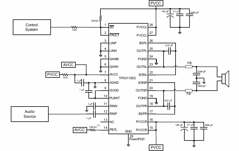
Figure 1: Standard wiring of a TPA3110D2 in bridge mode
The /SD signal at pin 1 is for shutting down (muting) the circuit. /FAULT at pin 2 is an open connector output. So it needs a pull-up resistor to function properly – the resistor rises the potential to a High state when the internal transistor at this pin is switched off. In the case of internal problems this transistor will go into a conducting state, so that the voltage at pin 2 then switches to LOW. This LOW signal will than mute the circuit, because it is also passed to pin 1.
I checked the voltages at all pins of the power amp circuit and found something strange: Pin 1 and 2 had permanently LOW level, which will mute the entire circuit. While comparing the parts at the VT20+ board with the standard application in the data sheet I recovered something very strange. Instead of going with one end to the positive PCVV voltage the pull-up resistor R55 in the Vox amp was soldered to ground level.(!) I suppose this is a real fault in the circuit design of the VT20+.
This is the relevant part of the power amp section of the VT20+.
Figure 2: Wiring in amp section of the VT20+ (not complete)
There is nothing special compared with the TPA3110D2 data sheet. One of both Gain inputs gets a signal, so that the overall gain can be switched between 26 dB (Gain 0 = High, Gain = Low) and 36 dB (Gain 0 = High, Gain = High). The only difference is the (IMHO) wrong connection from R55 to ground instead to +PVCC (+15V).
I decided to give it a try. I removed R55 and than soldered a 100k resistor from this pin to that side of the R57 (10 Ohm) that is connected with PVCC (+15V). And lo and behold! Suddenly the amp worked!
So I think the wiring of R55 in the VT20+ really may be a fault. But it can be changed easily.

Figure 3: Wiring of R55 before modification

Figure 4: new wiring of R55 after modification
Alternative: replacing with a fully assembled power amplifier
If the power circuit of a Vox VT20+ cannot be fixed it will be a good solution to just replace it with another fully assembled Class D amplifier. There are some other class D amplifier circuits on the market that can deliver 20...30 Watts.
Some alternative class D amplifiers
TPA3116 works up to 26 V, harmonic distortion 0,2%
TDA7297 1% harmonic distortion
TDA7498 harmonic distortion depends on condensators
YDA138-E Yamaha, has only 0,03...0,1% harmonic distortion, needs 12 V, 20 W in brige mode
At ebay I found fully assembled 20W class D amplifiers with the Yamaha YDA138-E chip for less than 10 Euro. But you will need an additional voltage regulator. Its power voltage must be about 12 V, but the power voltage in a Vox VT20+ is +15V.
Figure 5: A complete 2x 10 W/ 1x 20 W class D amplifier with Yamaha YDA138-E
To keep the valve technology working, the output signal must be fed into the board in front of the the current feedback resistor R64. To prevent a shorting against the built-in power amplifier you have to remove at least one end of both inductors FB9 and FB10, so that no current can go back into the TPA3110D2.
Also you must assure that the output signal has the right polarity.
More modifications
Power unit condensators
Some people claim they are not satisfied with how the VT20+ handles lower frequencies. Looking at the board I am not surprised. The class D amplifier does not need much static current (almost none), but of course it needs as much current as it has to feed into the speaker. When you look with an oscilloscope at the output signal you would be surprised, how much amplitude is needed to produce a strong bass.
Amplifiers that support strong bass frequencies normally have strong condensators in their power supply that can store enough energy to feed those currents. (The transformer has an inner resistance that limits the current, condensators have a much lower inner resistance.)
I assume, some stronger condensators in the power unit will substantially help the VT20+ to have more reserves in handling strong bass frequencies, giving the sound more volume.
Other repairs
Resetting a VC 20 that was in amp mute low mode
Send from: xxxx@gmail.com
Date: Fri, 13 May 2016 21:18:30
Hey!
I had an issue with the VT20+ so i ended up on your site and had everything unscrew until I found a VT80+ schematic and a test thing with freakin shit load of testing/edit settings I was able to manually put it out of amp mute low mode.
I reboot using audio test (2.test mode > 2.1how to boot & 2.4 audio test)
the amp button toggles low/high (red/green)
see page 8 & 13 from pdf (2 & 7 on right bottom page marks)
oh also i did the thing with a 1/8 stereo cable (but not the test cause they wanted a mono cable) just to see if the tap light was responding.
Send from: xxxx@gmail.com
Date: Sun, 15 May 2016 20:28:24
Actually it was the headphone jack stuck into mute mode.. a needle did the job... but the testing thing helped me to monitor the sensor